Chapter 3-7: Output Processes |
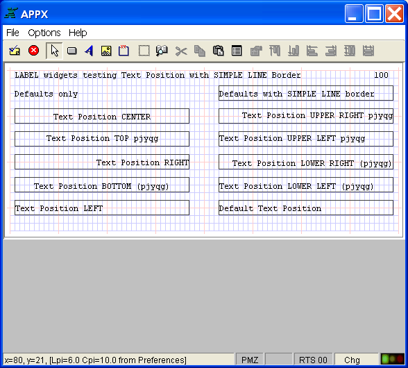
Designing GUI Output One of the first things that you may notice is that the Image Editor looks different when you are designing GUI output or inquiry processes. The figure below shows a 21x80 image with the grid turned on.
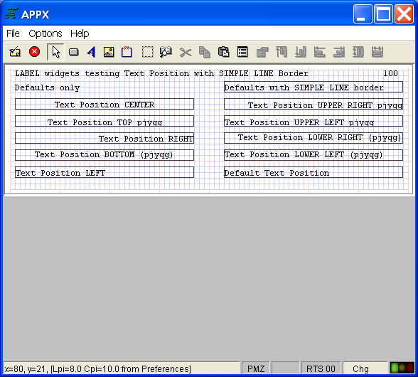
Output Image with Grid Turned On (21x80 at 6 lpi, 10 cpi) Notice that only about 2/3 of the screen is used to display 21 rows. To some, the screen may look 'squished' since 21 rows are displayed in about 2/3 of the space that is used to display 21 rows when designing an input or menu process. Why is this? Aspect ratio! We want the Image Editor to show the output image in exactly the same proportions that it will print at. For example, if you were to draw a box that looked square using the Image Editor, you would expect a square box to print. Notice on the status line that the output image is displayed at 6 lines per inch (lpi) and 10 characters per inch (cpi), anticipating that you will print the report using a form with those specifications. The figure below looks even more 'squished'. What happened?
Output Image with Grid Turned On (21x80 at 8 lpi, 10 cpi) Notice that the aspect ratio of this output image is based on 8 lpi and 10 cpi. But, WYSIWYG (what you see is what you get) prevails! So, how can you control the aspect ratio of an output image in the Image Editor at design time? There are two ways. Effective with APPX 4.2, an output process has a field in Additional Attributes called Preferred Form. If you specify a FORM name in the Preferred Form field, then APPX will compute the lpi and the cpi from the definition for that FORM in System Administration. It can then display the output image using an aspect ratio that corresponds to the FORM specs. Or, while on the output image in Application Design, you can select the File menu on the menu bar and then select Preferences. The lpi and the cpi can be set as a client preference by double-clicking on the appropriate Value cell ( printRowsPerInch and printColsPerInch, respectively). So, if you design all of your reports to print at 6 lpi and 12 cpi, simply set the preference and APPX will remember it from that point on. |
Application Design Manual "Powered by Appx Software"353 ©2006 By APPX Software, Inc. All Rights Reserved |